Using TCanvas in Delphi for Android
Drawing on TCanvas in Delphi XE5 for Android turned out to have some special aspects which at first left me in doubt and I want to share my experience.
Let’s draw some parallel lines.
Here I’d like to digress and notice that on Windows Stroke.Kind value is bkSolid by default, but on Android it’s bkNone. Thus, if you haven’t defined Stroke.Kind value, these lines will be visible on Windows, but will not on Android. I have no idea why they chose this approach.
procedure TForm2.FormPaint(Sender: TObject; Canvas: TCanvas;
  const ARect: TRectF);
var
  I: Integer;
begin
  if Canvas.BeginScene then
    try
      Canvas.Stroke.Thickness := 1.5;
      Canvas.Stroke.Kind := TBrushKind.bkSolid;
      Canvas.Fill.Color := TAlphaColorRec.Black;
      Canvas.Fill.Kind := TBrushKind.bkSolid;

      for I := 1 to 9 do
        Canvas.DrawLine(PointF(50 + I * 25, 0), PointF(50 + I * 25, ClientHeight), 1);
    finally
      Canvas.EndScene;
    end;
end;
That’s it:
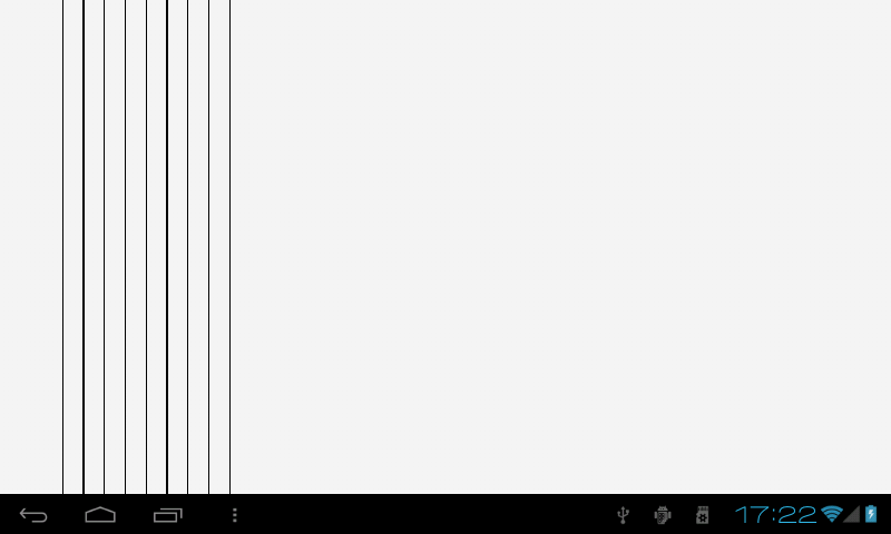
Obviously, some lines are thicker than others. On Windows the same code works just perfectly.
The reason is that unlike it does on Windows, the logical pixel on Android is not always equal to physical pixel. And if a line appears to be “between” physical pixels, it has to be blurred on neighboring pixels. It is a trade-off between accuracy and quality of rendering.
If we still want to draw equal lines, we could move them by the half of their thikness to ensure getting the appropriate physical pixels.
That’s how TLine and its ancestor TShape solve the problem:
function TShape.GetShapeRect: TRectF;
begin
  Result := LocalRect;
  if FStroke.Kind <> TBrushKind.bkNone then
    InflateRect(Result, -(FStroke.Thickness / 2), -(FStroke.Thickness / 2));
end;

procedure TLine.Paint;
begin
  case FLineType of
    TLineType.ltTop:
      Canvas.DrawLine(GetShapeRect.TopLeft, PointF(GetShapeRect.Right, GetShapeRect.Top),
        AbsoluteOpacity, FStroke);
    TLineType.ltLeft:
      Canvas.DrawLine(GetShapeRect.TopLeft, PointF(GetShapeRect.Left, GetShapeRect.Bottom),
        AbsoluteOpacity, FStroke);
  else
    Canvas.DrawLine(GetShapeRect.TopLeft, GetShapeRect.BottomRight, AbsoluteOpacity, FStroke);
  end;
end;
Making the appropriate changes we can draw equal lines too:
procedure TForm2.FormPaint(Sender: TObject; Canvas: TCanvas;
  const ARect: TRectF);
var
  I: Integer;
begin
  if Canvas.BeginScene then
    try
      Canvas.Stroke.Thickness := 1.5;
      Canvas.Stroke.Kind := TBrushKind.bkSolid;
      Canvas.Fill.Color := TAlphaColorRec.Black;
      Canvas.Fill.Kind := TBrushKind.bkSolid;

      for I := 1 to 9 do
      begin
        Canvas.DrawLine(PointF(50 + I * 25 - (Canvas.Stroke.Thickness / 2), 0),
          PointF(50 + I * 25 - (Canvas.Stroke.Thickness / 2), ClientHeight), 1);
      end;
    finally
      Canvas.EndScene;
    end;
end;
The result is:
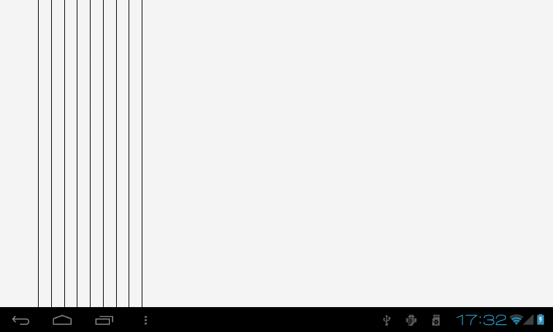
Much better :)
This can’t be done automatically: in this case it will “jump” during an animation. But anyways I’d like to have some flag to choose between accuracy and quality. It’s quite boring to do this calculation manually.
update
Alysson Cunha suggests one more approach:
function TForm2.RoundLogicPointsToMatchPixel(const LogicPoints: Single;
  const AtLeastOnePixel: Boolean = False): Single;
var
  ws: IFMXWindowService;
  ScreenScale, Pixels: Single;
begin
  ws := TPlatformServices.Current.GetPlatformService(IFMXWindowService) as IFMXWindowService;
  ScreenScale := ws.GetWindowScale(Self);

  // Maybe you will want to use Ceil or Trunc instead of Round
  Pixels := Round(LogicPoints * ScreenScale);

  if (Pixels < 1) and (AtLeastOnePixel) then
    Pixels := 1.0;

  Result := Pixels / ScreenScale;
end;

procedure TForm2.FormPaint(Sender: TObject; Canvas: TCanvas;
  const ARect: TRectF);
var
  I: Integer;
begin
  if Canvas.BeginScene then
    try
      Canvas.Stroke.Thickness := RoundLogicPointsToMatchPixel(1.0, True);
      Canvas.Stroke.Kind := TBrushKind.bkSolid;
      Canvas.Fill.Color := TAlphaColorRec.Black;
      Canvas.Fill.Kind := TBrushKind.bkSolid;

      for I := 1 to 9 do
        Canvas.DrawLine(PointF(RoundLogicPointsToMatchPixel(50 + I * 25), 0),
          PointF(RoundLogicPointsToMatchPixel(50 + I * 25), ClientHeight), 1);
    finally
      Canvas.EndScene;
    end;
end;